
Valve springs are among the hardest-working components in any performance engine. Understanding how and why they fail helps you build engines that last — and avoid catastrophic damage.
Fatigue Fracture
Fatigue fracture is the most common valve spring failure mode. A spring cycling at 7,000 RPM opens and closes each valve 3,500 times per minute — that is 210,000 stress cycles per hour. Over time, micro-cracks initiate and propagate until the wire breaks.
What It Looks Like
The break typically occurs in the lower or upper third of the spring, where stress concentrations are greatest. Under magnification, the fracture surface shows characteristic “beach marks” — concentric rings radiating outward from the initiation point. The fracture zone appears smooth and progressively worn, transitioning to a rough, crystalline final fracture zone.
The break usually occurs at about coil 1.3 from the upper end, and fracture surfaces form an angle of approximately 45° to the tangent direction of the outside circle of wire.
What Causes It
- Cyclic loading beyond the material’s endurance limit
- Surface defects acting as stress risers: tool marks, corrosion pits, inclusions in the wire, or nicks from improper handling
- Insufficient shot peening — without adequate compressive residual stress on the wire surface, cracks propagate rapidly
- Operating springs beyond their designed installed height or at excessive pressures
- Non-metallic inclusions beneath the surface from which fatigue initiates and propagates toward the core
- Valve float events causing impact loading that dramatically accelerates fatigue
How to Prevent It
- Select springs rated for your actual RPM range and cam profile — a spring rated for 6,500 RPM is dangerously inadequate at 8,000 RPM
- Ensure proper shot peening — dual-stage peening (larger shot for depth, then smaller for surface finish) provides superior fatigue life
- Inspect regularly — in professional racing, valve springs are treated as consumables with 15-25 hours of service life
- Maintain correct installed height within 0.020″ of specification
- Handle springs carefully during installation — do not nick, scratch, or drop them
Racing Service Life
In professional motorsport, valve springs are treated as consumable items with a defined service life:
- Sprint car teams: Replace every race night
- Circle track: 15-25 hours of competition
- Road racing: Check every event, replace every 2-3 events
- Drag racing: Log passes, inspect after every session
Always log spring hours and replace at the manufacturer’s recommended interval. The investment in springs is trivial compared to the cost of a dropped valve.
Spring Surge & Resonance
Every spring has a natural frequency. When the cam’s operating frequency or its harmonics coincide with the spring’s natural frequency, the spring enters resonance — sections of the coil oscillate out of phase, creating zones of extreme compression and extension that can destroy the spring.
What It Looks Like
Surge failures produce a distinctive pattern: the wire fracture occurs mid-coil rather than at the ends. In severe cases, you may find multiple fracture points. The spring may appear to have “unwound” slightly, and adjacent coils show polishing marks or galling from coil-to-coil contact during surge events.
In a running engine: Surge manifests as an audible harmonic ringing or buzzing from the valvetrain. On a Spintron or similar analyser, you will see erratic valve motion at specific RPM ranges.
What Causes It
- Cam operating frequency matching the spring’s natural frequency
- Aggressive cam profiles with high jerk values that excite broad frequency spectrums
- Lightweight single springs with few active coils (lower natural frequency)
- Excessive coil bind clearance (more than 0.150″ can allow surge to develop)
The physics: When the cam accelerates the lifter, a compression wave travels through the spring at the speed of sound in the material. If the wave’s round-trip time aligns with the cam’s acceleration events, constructive interference builds — some coils compress together while others pull apart. The effective spring rate drops to near zero in stretched zones, meaning the spring temporarily loses control of the valve.
Why Dual Springs Prevent Surge
Dual springs are the single most effective countermeasure against surge, working through two mechanisms:
1. Different natural frequencies: Each spring in a nested set has a different natural frequency (different wire diameter, coil diameter, number of active coils). They cannot resonate simultaneously — when one spring surges, the other maintains valve control.
2. Inter-spring damping: Friction between the inner and outer spring surfaces absorbs 10-15% of resonant energy per cycle — enough to prevent destructive buildup.
Spring Frequency Requirements
A spring’s natural frequency must be at least 13 times the cam’s maximum operating frequency (in Hz) to provide adequate surge margin.
Formula:
Required minimum spring frequency = (RPM / 2) / 60 × 13
Other surge-resistant designs:
- Beehive springs — conical design shifts natural frequency upward as spring compresses
- Ovate/flat wire — increases frequency relative to mass
- Triple springs — three frequencies plus additional damping surfaces (standard for Pro Stock / Top Fuel)
Coil Clash & Coil Bind
Coil bind occurs when the spring compresses fully solid — all coils touching with zero clearance. The resulting impact loads can crack or shatter coils instantly, and the forces transmit through the entire valvetrain as a destructive shock wave.
What It Looks Like
After a coil bind event, look for:
- Polished or galled contact marks on the ID and OD of adjacent coils
- Deformation or flattening of the wire cross-section at contact points
- Permanent set — the spring’s free length is shorter than original (more than 0.030″ indicates fatigue)
- In severe cases, multiple adjacent coils crack or shatter simultaneously
What Causes It
- Insufficient coil bind clearance — spring reaches solid height before the valve reaches full lift
- Aftermarket cam with more lift than the springs can accommodate
- Incorrect installed height (too tall = valve travels further, consuming bind clearance)
- Valve seat recession over time increasing effective valve travel
- Incorrect spring selection for the application
The critical calculation:
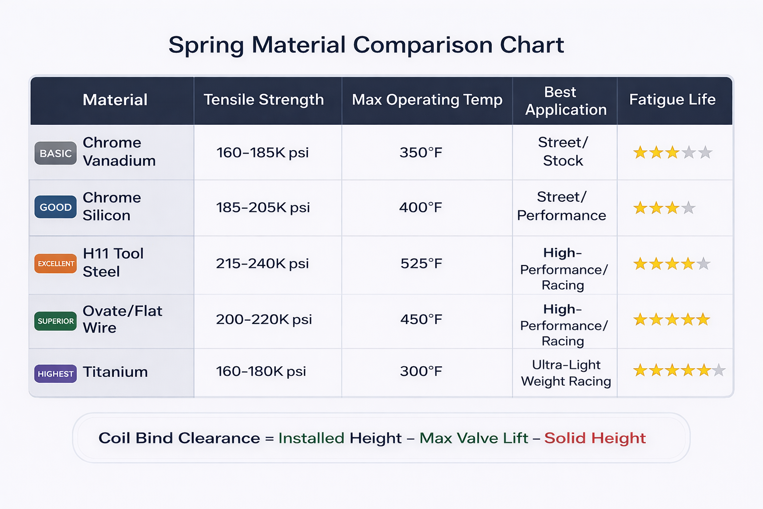
Coil Bind Clearance = Installed Height − Maximum Valve Lift − Solid Height
Minimum: 0.060″
Recommended: 0.080″ to 0.100″
Heat Damage & Corrosion
Thermal exposure and corrosive environments attack spring integrity from the surface inward. Heat causes permanent relaxation (pressure loss), while corrosion pits act as micro-notches that dramatically reduce fatigue life.
Heat-Related Failure
What it looks like: A blue or straw-coloured heat tint on the wire surface indicates temperatures above 500°F. The spring loses free length and installed pressure — this is called “relaxation” or thermal set.
In extreme cases (above 700°F), the spring’s temper is drawn, destroying its hardness and fatigue strength. The wire may show plastic deformation.
Causes:
- Excessive valvetrain friction from inadequate lubrication or misaligned components
- Proximity to exhaust ports — exhaust springs run 100-150°F hotter than intake springs
- Oil starvation due to plugged galleries
- Extended high-RPM operation without adequate cooling
Prevention: Ensure adequate oil flow to the valvetrain. Chrome-silicon maintains properties to ~475°F. For higher temps, use H11 tool steel (rated to ~600°F). Consider titanium retainers which conduct less heat.
Corrosion Pitting
What it looks like: Small, irregular cavities on the wire surface — rust-coloured or dark. Even tiny pits (0.001″ to 0.003″ deep) act as severe stress concentrators because of the high surface stresses in spring wire. A fatigue crack initiates from the base of the pit.
Causes:
- Moisture during storage — springs in unsealed packaging in humid environments corrode quickly
- Acidic combustion byproducts, especially from ethanol-blended fuels
- Coolant contamination from a head gasket leak
- Fingerprints — salt and oils from skin are mildly corrosive
Prevention:
- Store springs in sealed, desiccated packaging until installation
- Apply assembly lubricant or oil during installation
- Handle springs with clean, oil-free gloves
- Fix coolant leaks before they contaminate the valvetrain
Hydrogen Embrittlement
What it looks like: Sudden, catastrophic failure with no visible warning. The fracture surface is intergranular (along grain boundaries) — appearing as “rock candy” under electron microscope. The wire snaps cleanly without bending or necking. These failures can occur within the first few hours of operation.
Causes:
- Hydrogen atoms introduced during acid pickling, electroplating, or cleaning diffuse into the steel lattice
- Improper baking after plating — components must be baked at 375-400°F within 4 hours of plating
- High-strength steels (above 40 HRC) are increasingly susceptible — performance spring wire runs 55-60 HRC
Prevention: Source from reputable manufacturers with documented hydrogen management. Never acid-clean valve springs. If any plating is done post-manufacture, ensure proper baking protocols.
Environment-Assisted Cracking (EAC)
Research has shown that the premature fatigue failure of high-strength valve springs can be attributed to intergranular surface cracks formed by environment-assisted cracking.
This mechanism significantly reduces fatigue strength from the designed 720 MPa to just 320-350 MPa — less than half the intended capacity.
Contributing factors include reduced shot peening effectiveness caused by soft and brittle PbO adhesion on the spring surface.
Key takeaway: Surface condition is everything. Even microscopic contamination or surface irregularities can halve a spring’s fatigue life.
Common Installation Mistakes
Many valve spring failures are not caused by defective parts — they are caused by installation errors. These mistakes are preventable with proper procedure, but they account for a significant percentage of premature failures.
Wrong Installed Height
The mistake: Installing springs without measuring actual installed height on each cylinder. Variations in machining mean height varies 0.020″ to 0.040″ across a head — even on new castings.
Too tall: Insufficient seat and open pressure → valve float → potential piston contact.
Too short: Excessive pressure → accelerated wear on cam, lifters, guides, and springs → reduced coil bind clearance.
The fix: Measure every spring location with a spring height micrometer. Shim to within 0.010″ across all locations. Record shim thickness for future reference.
No Lube on Retainer/Lock Interface
The mistake: Assembling the retainer, locks, and valve stem dry or with insufficient lubrication.
What happens: During initial start-up, locks must seat and centre themselves while cycling at 1,000+ RPM. Without lubrication, metal-to-metal contact causes galling (material transfer) that prevents proper seating. Improperly seated locks can release — dropping the valve into the cylinder.
The fix: Apply assembly lubricant or moly paste to lock grooves on the stem, outer taper of each lock, inner taper of retainer, and retainer-to-spring contact surface.
Do NOT use anti-seize (too thick) or grease (can hydraulically prevent lock engagement).
Reusing Old Springs
The mistake: Reinstalling springs that have been in service, especially when upgrading to a more aggressive cam.
Why it fails: Used springs have accumulated invisible fatigue damage. Micro-cracks exist below the shot-peened surface. Free length has decreased. The compressive residual stress layer has been partially consumed by cyclic loading.
A used spring that tests within spec today may fail next week because it is near the end of its fatigue life curve.
The rule: Always install new springs with a new cam. If reusing springs in a mild application, test every spring for free length, pressure, and squareness — discard any that fail.
Mixing Spring Sets
The mistake: Installing springs from different manufacturing lots, or substituting a single replacement from a different set.
Why it fails: Springs from different lots have subtle differences in free length, rate, and pressure. This creates inconsistent valvetrain dynamics across cylinders. In dual spring assemblies, mixing inner and outer springs from different sets can create interference issues — OD/ID tolerances are matched at the set level.
The rule: Always install springs as a complete matched set. If one breaks, replace the entire set — at minimum, replace all springs on the affected bank (all intake or all exhaust).
Spring Materials Guide
The spring material determines its tensile strength, fatigue life, heat resistance, and ultimately its RPM capability. Choosing the right material for your application is one of the most important decisions in a valvetrain build.
Spring Rate, RPM & Cam Profiles
Spring rate (lbs/inch of deflection) determines how quickly force builds as the spring compresses. The required rate is driven by two factors:
RPM: Kinetic energy of moving valvetrain components increases with the square of RPM. Doubling RPM quadruples the energy springs must control.
Cam aggressiveness:
- Higher lift → more open pressure required
- Faster opening/closing rates → more spring force to prevent lofting
- Higher acceleration on closing side → higher seat pressure
- Aggressive jerk values → higher natural frequency springs needed
Titanium Retainers
While not a spring material, Ti-6Al-4V retainers are a critical valvetrain component. At 40-45% lighter than steel, they directly reduce the mass the spring must control:
- Lower spring pressures for the same RPM capability → less friction and parasitic drag
- Same pressures provide a higher effective RPM ceiling
- Reduced impact loading extends spring fatigue life
- Lower reciprocating mass reduces heat generation
Critical note: The lock interface groove must be properly hardened or PVD-coated (titanium nitride) to resist galling. Tool-steel locks are preferred with titanium retainers.
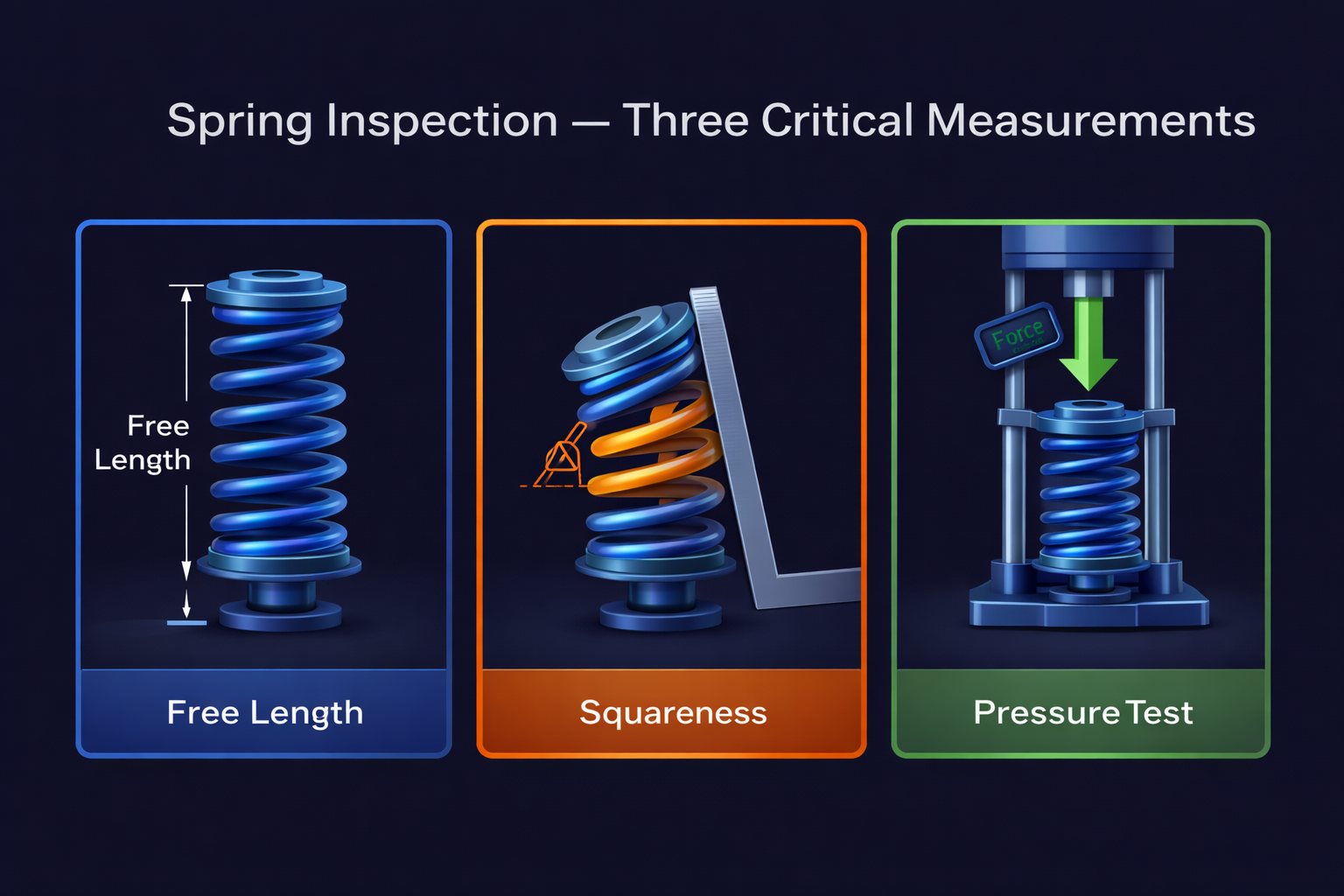
Inspection & Testing Procedures
A dedicated valve spring tester is essential for any serious engine builder. Never install springs without verifying free length, squareness, and pressure — even from a new box.
Spring Tester Procedure
- Zero the tester with no spring installed
- Place the spring centred and square on the platform
- Compress to installed height — record the force (seat pressure)
- Compress to installed height minus max valve lift — record the force (open pressure)
- Continue slowly toward solid height to verify coil bind clearance — do not slam to solid
- Record all values for every spring in the set
Tolerance: All springs should be within 5 lbs of each other at both seat and open heights. A spread greater than 10 lbs indicates mixed sets or manufacturing inconsistency.
Visual Inspection Checklist
Before testing, visually inspect each spring under good lighting (magnifying lamp recommended):
- Surface corrosion or pitting — any pitting is cause for rejection in racing
- Nicks, scratches, or handling damage on the wire surface
- Tool marks from manufacturing — should be eliminated by shot peening
- Heat discolouration — straw, blue, or grey tints indicate overheating
- Coating damage or wear
Also inspect: Retainer taper surfaces for galling, lock grooves on valve stems for wear or mushrooming, lock surfaces for deformation, and spring seat surfaces on the head for cracking or erosion.
Free Length Measurement
Stand each spring on a precision flat surface and measure height without compression.
Accept: Within 0.020″ of published spec.
Reject: Short springs have lost preload — possible thermal relaxation or fatigue damage.
Important: Record the free length of every new spring before installation. This baseline enables meaningful comparison at future inspections.
Squareness Check
Stand the spring next to a machinist’s square. Rotate slowly 360° and observe the gap between the top coil and the square blade.
Accept: Within 1.5° of perpendicular (approximately 0.050″ deviation per 2″ of free length).
Why it matters: An out-of-square spring applies a side load to the retainer and valve stem, causing accelerated guide wear, retainer rock, and uneven stress distribution. It also affects installed height measurement accuracy.
Single vs Dual Springs
Understanding the difference between single and dual valve spring assemblies is essential for selecting the right spring for your application. Dual springs offer critical advantages for high-RPM and performance builds.
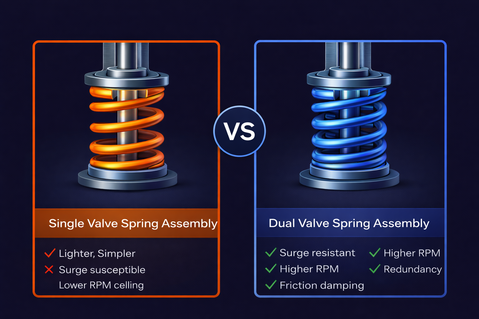
When to Use Single Springs
Single springs are appropriate for stock to mild performance applications where the engine operates within the OEM-designed RPM range:
- Stock engines with factory cam profiles
- Mild street builds under 6,500 RPM with conservative cam timing
- Applications where minimum valvetrain mass and friction are the priority (some modern beehive designs)
- Engines with hydraulic lifters that limit RPM anyway
Modern beehive springs have blurred this line — their conical design naturally resists surge better than traditional cylindrical singles, making them viable up to ~7,000 RPM in many applications.
When You Need Dual Springs
Dual springs become essential when any of these conditions apply:
- RPM above 6,500 with aggressive cam profiles
- Solid or mushroom lifters with high-lift cams
- Turbo, supercharged, or nitrous applications where combustion pressure works against the spring
- Any racing application where reliability is critical — the inner spring provides a safety margin if the outer breaks
- High valve lift (above 0.500″) requiring high open pressures
For VW performance engines — whether 8V or 16V — dual springs are the correct choice for any build targeting sustained high RPM. This is why STK Performance offers purpose-built dual spring kits for these platforms.
The Physics of Dual Spring Advantage
Two springs working together provide more than just twice the rate. The key advantages are dynamic, not static:
1. Surge immunity: Each spring has a different natural frequency (different wire diameter, coil count, and pitch). When one spring approaches resonance, the other is off-frequency and maintains valve control.
2. Energy absorption: Friction between inner and outer spring surfaces dissipates 10-15% of vibrational energy per cycle — preventing destructive resonance buildup.
3. Non-linear rate: As the assembly compresses, the shorter inner spring often goes solid first, creating a progressive rate increase that improves high-lift control.
Dual Spring Selection Rules
When selecting or inspecting a dual spring assembly, verify:
- Correct nesting clearance — the inner spring OD should clear the outer spring ID by 0.030″-0.060″. Too tight causes binding; too loose eliminates the friction damping benefit
- Opposite wind direction — inner and outer should be wound in opposite directions to prevent interlocking if a coil breaks
- Matched sets only — inner and outer springs are tolerance-matched at the factory. Never mix components between sets
- Correct spring locator — the inner spring requires its own locator to prevent it from walking off-centre
Prevention Starts with Quality Springs
Most valve spring failures share a common thread — the spring was pushed beyond the limits of its design, material, or condition. Whether it’s fatigue from excessive cycles, surge from inadequate damping, or heat damage from poor lubrication, the solution is to build with springs that are up to the task.
At STK Performance, we manufacture chrome-silicon dual valve spring kits, forged stainless steel valves, chromoly retainers, and complete valvetrain upgrade packages engineered for performance applications. If you’re building an engine that will see high RPM, boost, or track use — don’t leave your valvetrain to chance.